There are a few bits of interesting data that I’ve recorded while measuring boost pressure for fixed wastegate duty cycles. This is part of my effort to fine tune the KFLDRL numbers for the new wastegates that the TTE550’s use.
Each fixed wastegate duty cycle produces a different boost level. The range of boost levels that were recorded in third gear are shown below. Note: The recording in third at 10% was not long enough to make including the results worthwhile.

The chart above shows fixed WGDC’s of: 0%, 20%, 30%, 40%, 50%, 60%, 70%, 80%, and 85%.
For each of these boost levels I also recorded the air temperature going into the turbocharger compressor, along with the temperature after exiting the compressor. The approximate rise in temperature caused by the compression of the air for each boost level is shown below.
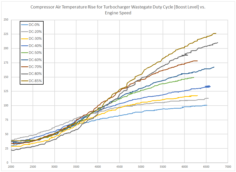
Note: This is an approximate rise due to the location of the air temperature sensor being slightly downstream from the turbocharger compressor outlet. The air temperature exiting the turbocharger is likely higher than what is recorded due to cooling taking place in the charge pipe prior to the air passing over the temperature sensor.