I’ve utilized an RS4 Y-pipe ever since I had the BW K04 turbochargers installed on my car several years ago. The larger Y-pipe was part of the APR Stage 3 kit and when I made the change to the TiAL 605 turbo’s I obtained some silicone reducers with the help of Johnny Bravo so that I could use the RS4 Y-pipe with the TiAL 2.25″ turbo inlet pipes.
Even after removing the 605’s and switching to the smaller FrankenTurbo F4H-BT turbo’s I wanted to optimize the intake path for minimal pressure loss. To that end I again reached out to Johnny Bravo for help with obtaining a set of TiAL turbo inlets, the previous set having been sold with my 605 turbo’s. I also retained the RS4 Y-pipe.
With the goal of maximizing the performance of the F4H turbo’s I felt keeping the pressure loss to a minimum on the intake side would be important. The measurements of the stock versus RS4 y-pipes did not lead me to believe the stock y-pipe would be a beneficial component, especially when the RS4 y-pipe was available.
Just based upon dimensions the stock y-pipe has a funneling affect. The combined area of the y-pipe outlets is less than the inlet area. The stock y-pipe inlet has an inner diameter of 80mm, which is 5026 sq mm. Each of the outlets has an inner diameter of 51.5mm, for a combined area of 4166 sq mm. That makes the combined outlet area only 83% of the inlet area.
By comparison the RS4 y-pipe inlet has a diameter of 85mm, yielding an area of 5674 sq mm, and the outlet diameter is 65mm, which produces a combined outlet area of 6636 sq mm, or 117% of the inlet area.
With the goal of not restricting airflow the RS4 y-pipe was the obvious choice.
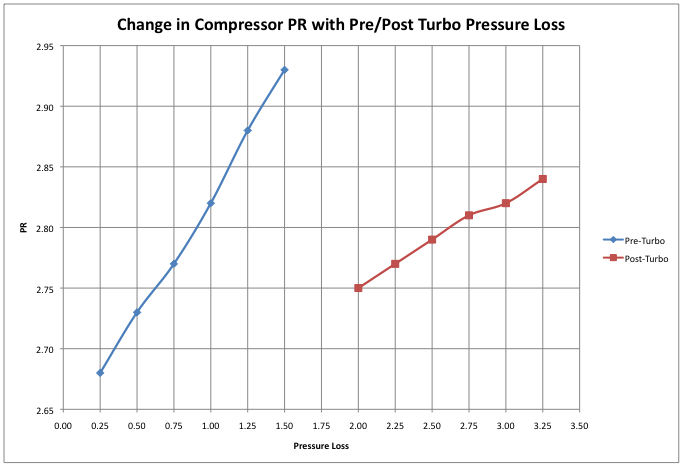
Minimizing pressure losses on the intake side of the turbo charger is especially important due to the impact on the turbo compressor pressure ratio. Using a basic equation for calculating the Pressure Ratio across the compressor, and using rough estimates for the pressure losses that occur in the pre-compressor (0.25 to 1.5 psi) and post compressor (2.0 to 3.25 psi) paths, the resultant affect on PR can be estimated. Note that the span of pressure loss being evaluated is the same for the pre and post compressor pressure loss values, each spans a range of 1.25 psi from minimum to maximum. The results of this type of model are shown below:

The most notable aspect of this chart is the rate of change of PR for the pre-turbo case versus the post-turbo case. The pressure ratio at the turbo compressor is much more sensitive to changes in pressure losses on the intake side of the compressor. Roughly two and a half times more change occurs pre-turbo as compared to post turbo. For me, the takeaway from this is that minimizing pressure losses on the intake side of the turbocharger can provided more benefit to the turbo than equivalent improvements on the post-turbo charger side of intake. If you are looking to optimize turbo performance, it is important to address the intake side of the turbo.
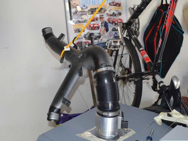
To see how the stock y-pipe compared to the RS4 y-pipe I built an adapter to fit my 85mm MAF housing so I could attach the MAF housing, accordion (RS4) and the two y-pipes to the flow bench.

Interestingly, while the inner diameter of the stock y-pipe inlet is 5mm smaller than the RS4 y-pipe, the outer diameter is only 2mm less. The stock y-pipe is a plastic material and uses a metal ring inside the ends of the inlet and outlets, presumably to provide strength for when hose clamps are attached. The RS4 y-pipe being made of metal has no such additional reinforcement.

*Note* For anyone who’s saying ‘Hey, the PCV port isn’t capped’, the photo was taken before everything was in place, I did cap that port during testing.
The 2mm difference in outer diameter between the stock and RS4 y-pipes meant that the RS4 accordion fit the stock y-pipe inlet without trouble.
The Results
Not surprisingly the RS4 y-pipe outflowed the stock y-pipe by a good amount.

Here is how the pressure losses increase with CFM. Depending upon the application, these results may or may not matter. On a stock K03 S4 there probably is not enough airflow going through the y-pipe to matter, but on a car making boost levels in the mid to upper 20’s or 30’s the amount of air drawn through the y-pipe becomes substantial, and as the chart illustrates, at higher CFM values there is a couple tenths and up to half of a psi of difference.

The bottom line is that when optimizing the vehicle to get the most from the turbochargers, the Y-pipe is a component that shouldn’t be ignored.
