
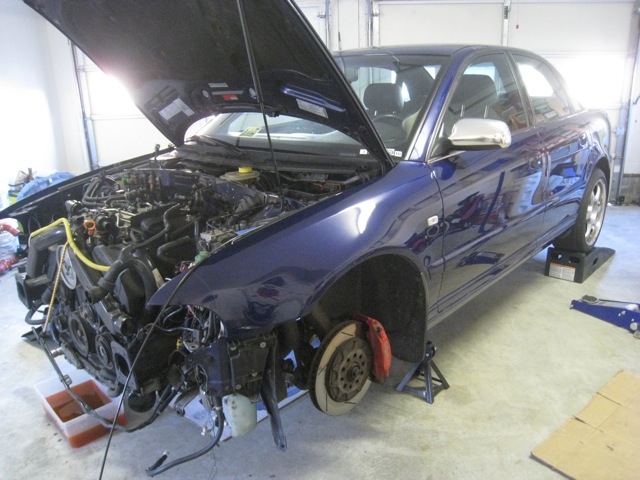
February 19th, 5:16 pm, ready to begin.
5:56 pm, first problem encountered. The drivers and passenger side axle bolts are different, hex key on one side, socket on the other.
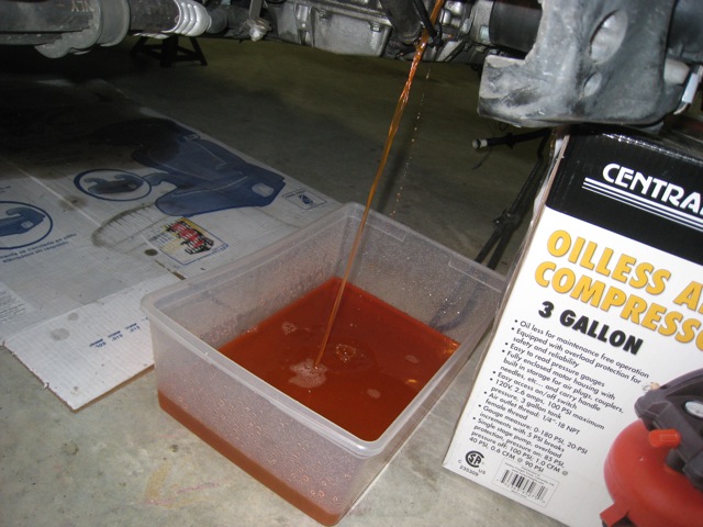
This car holds more coolant than you’d imagine, I think it continued to drain out throughout the entire work process.
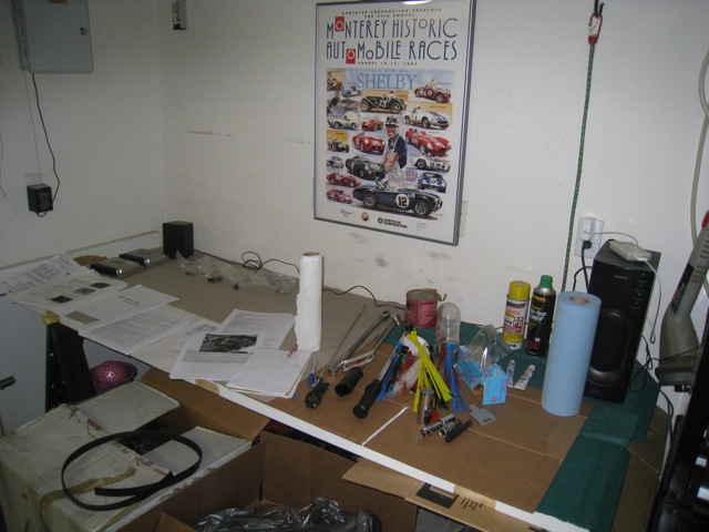
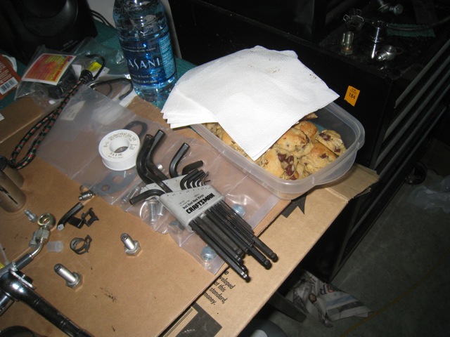
The work bench before it became a disorganized array of parts and tools, note all of the engine pull guides that I printed out and had on hand.
11:46 pm, enough for the first day.
Day 2
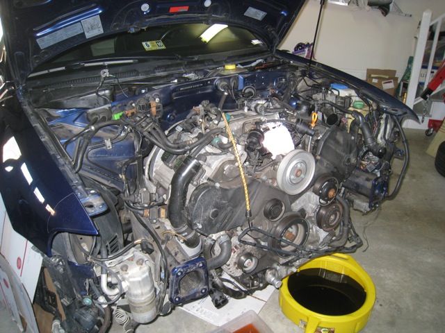
Back doing prep work on day two.

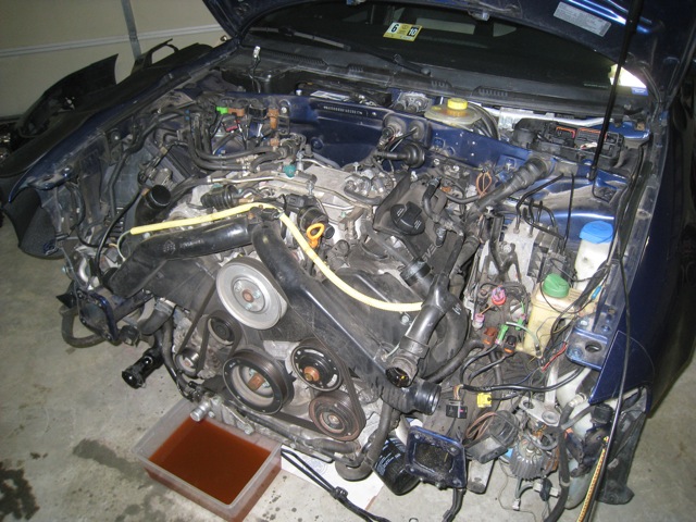
Working on the top side of the motor.
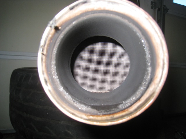
Moving underneath the car.
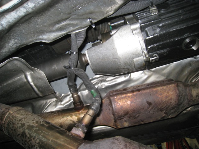
AWE catalytic converters look good still.
Wrapping up a short day 2.
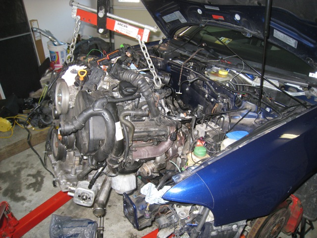
Day 3
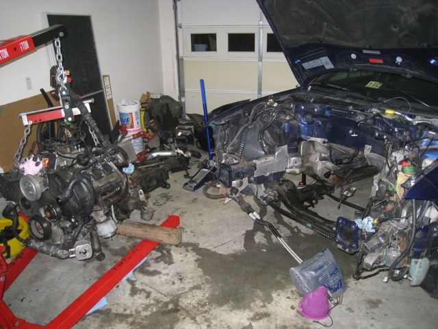
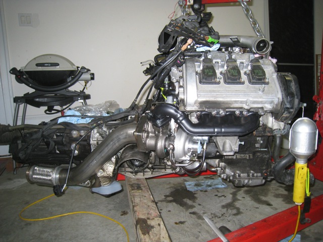
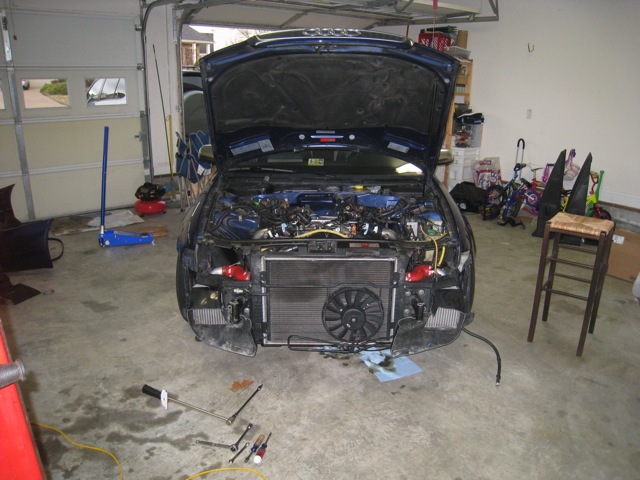
Day 3, out comes the motor.
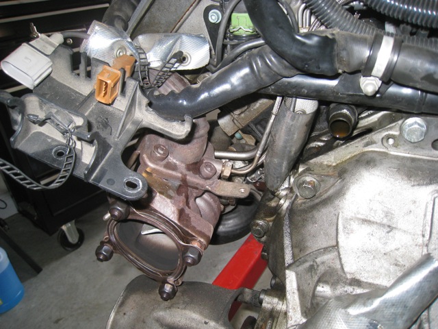
The bolts attaching the turbochargers to the exhaust manifold were extremely difficult to remove. The allen wrench went first, then the socket adapter. With a second allen wrench and a hammer we were finally able to loosen the bolts.
The lost tools

The end of day 3.
Day 4
Saying goodbye to the APR Stg3 components.
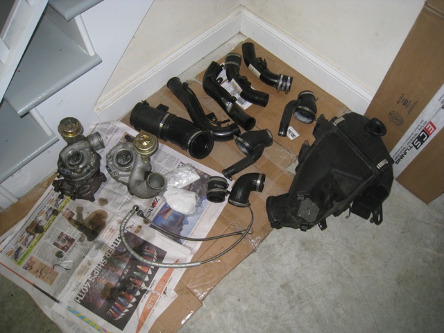
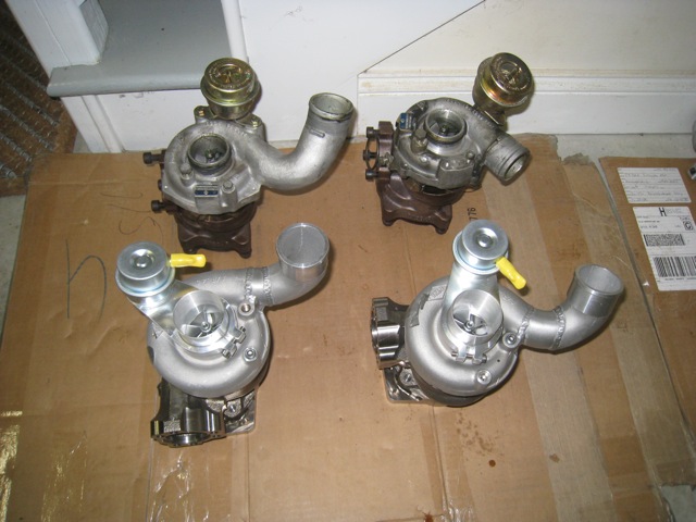
Turbocharger exchange.
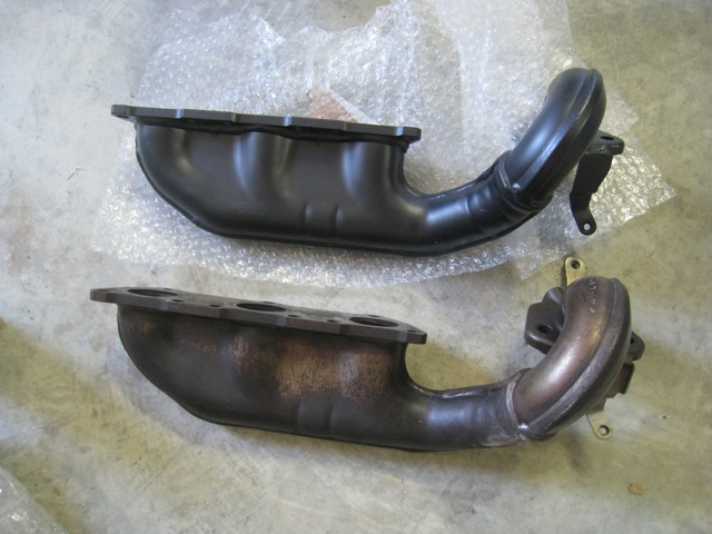
VAST ported and polished, ceramic coated exhaust manifolds.
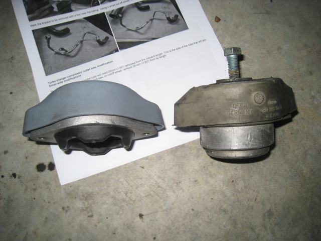
034 Street Density Transmission Mounts
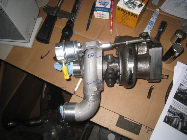
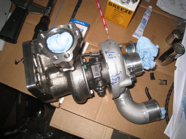
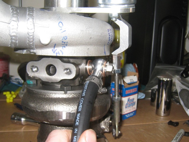
I decided to mark up the various ports on the turbochargers so that when I got around to putting them onto the car I would know just where to make each attachment.

As I was test fitting the coolant line I discovered a problem. The banjo bolt would not fit underneath the waste gate actuator arm.
After contacting EPL to bring my problem to their attention they instructed me on the solution. By loosening the clamp at the end of the waste gate actuator arm it would be possible to raise the arm high enough to get the bolt on.
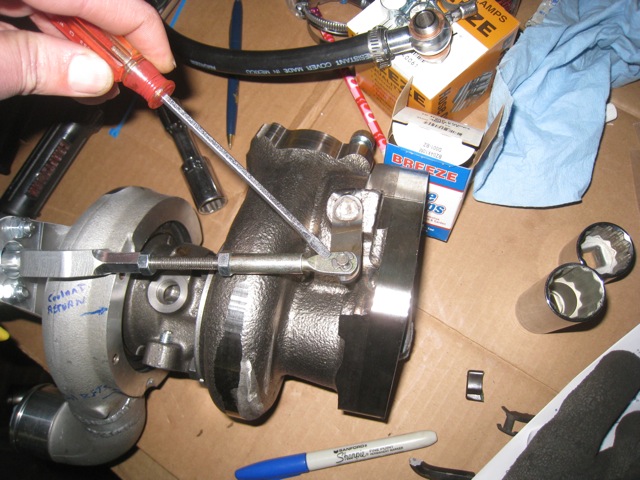
I was able to raise the bar far enough to get the bolt on without needing to completely remove the waste gate actuator arm.
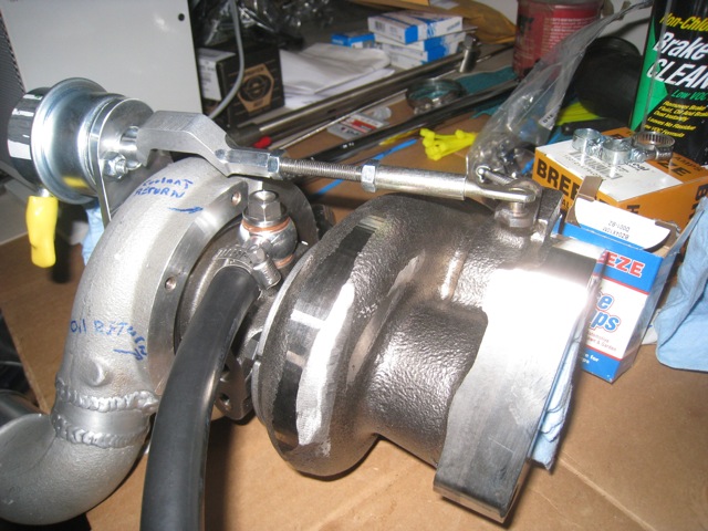
Installation of the driver’s side turbo and coolant line.
On of my gripes about this “complete” and “bolt-on” kit was that the turbo to DP gaskets were not included. As it turned out, neither were crush washers for attaching the oil lines to the distribution block. These missing items I had discovered early enough, before starting the install, to ask EPL about and they sent them to me at no cost. One of my recommendations back to Jonathan was to include these low cost but essential items with the kit. I believe that going forward that will be the case, that they will be included.

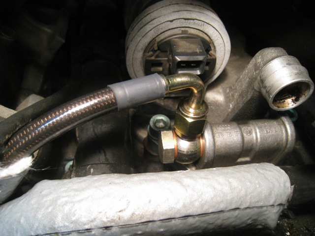
Here’s where the oil line and coolant line connect to the engine.
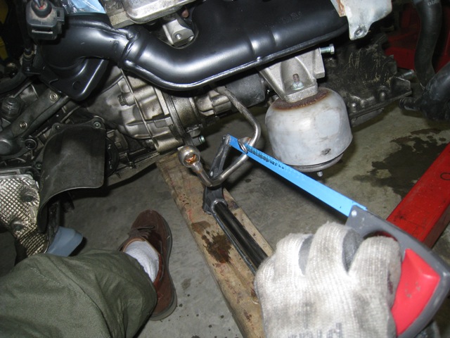
This is one of the required changes that needs to be done to the car. While minor, I do find it a bit disingenuous to say the kit is bolt on and requires no fabrication. Had I not had a hacksaw I would have had to buy or borrow one to progress with the install.
This was another problem I encountered while doing the installation.
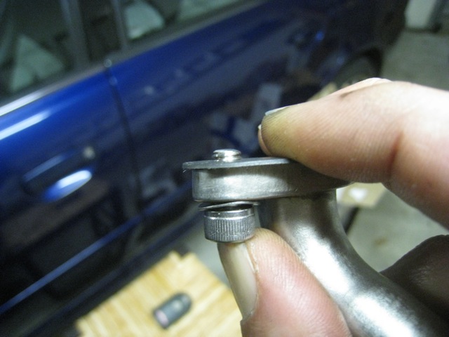
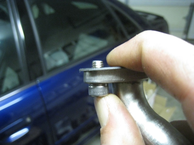
Even when removing the washer the bolt was still uncomfortably short for what it was there for, to attach the oil return line to the turbocharger housing.
I was able to locate an appropriate length set of bolts on my old engine fan and remove them to use for attaching these lines.
The oil return line installed.
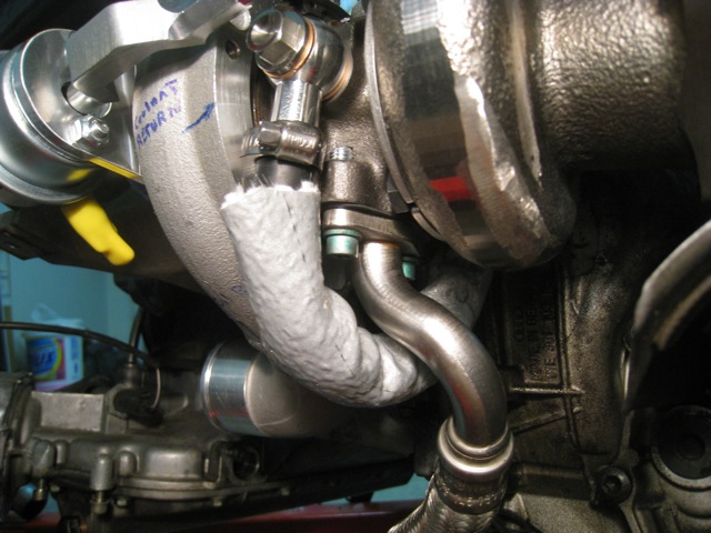
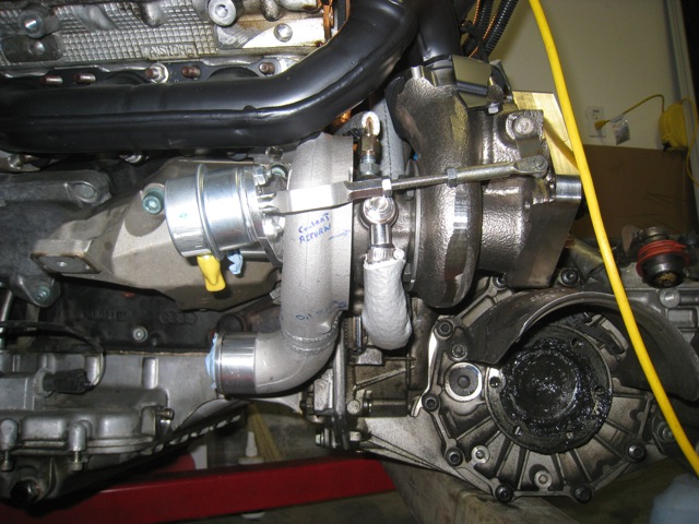
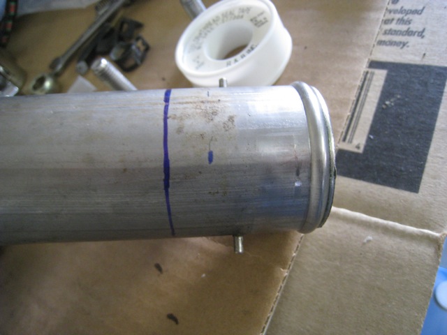
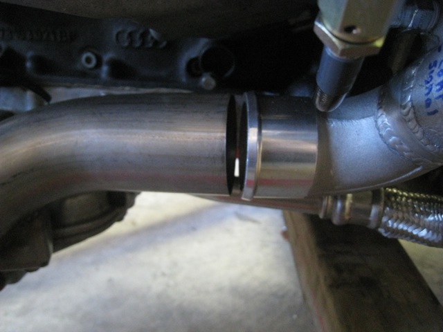
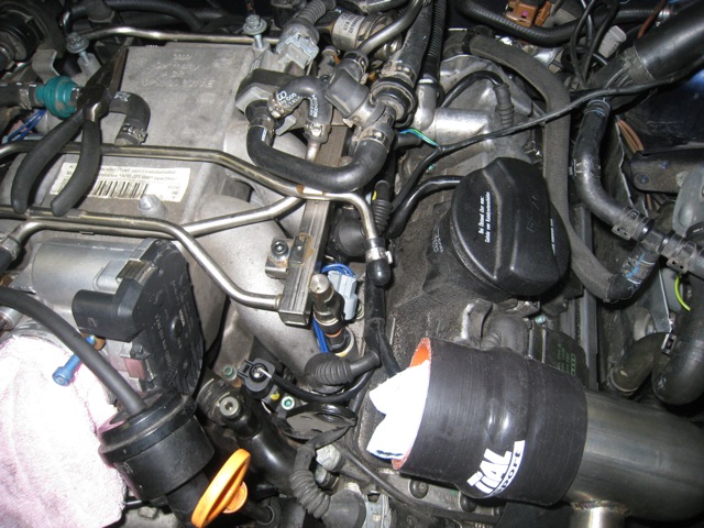
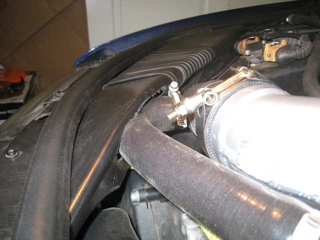
This was another problem I ran across, and one of the more serious because I had noticed the discrepancy when the kit was delivered. The coolant line was about an inch and a half shorter than spelled out in the installation guide. I had contacted EPL to question the difference and they believed the guide was not correct, and that the hose length was correct. As you can see in the picture, the coolant line passes over the hard pipe, and at this point the coolant line is being pinched. The line was very taught, to the point that I questioned if I had installed it correctly, but the pictures that I had for reference showed the coolant line being routed similar to how mine was. Fortunately I had spoken with Jonathan about another issue, and just happened to mention this one as well. He was quite concerned about the length of the hose and advised me to purchase a longer coolant line if I needed a better fitting part faster than what he could ship out a replacement piece. After getting a longer piece of hose the part fit much better. Fortunately this was caught when it was, I would be very concerned about what would happen to the turbocharger if the coolant supply was reduced because of this hose being pinched.
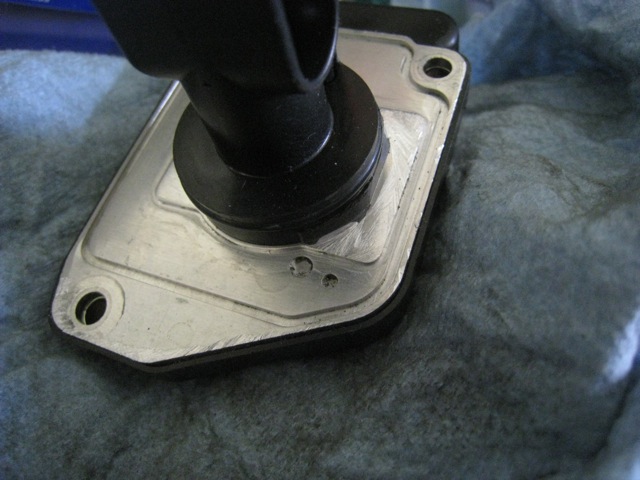
This was another aspect of the kit that was not a huge deal, but kind of annoying again when it is being advertised as bolt-on. The engine mounts need to be filed down some to give clearance to the TiAL inlet pipes.
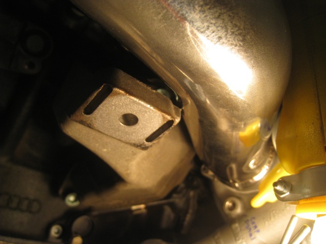
I did the work with a hand file. It took a little while, but I wanted to try and take off as little metal as I could so I stayed away from the dremel tool option.
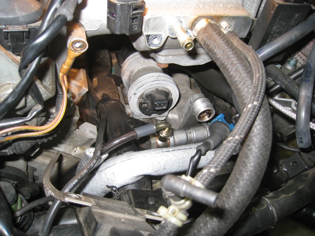
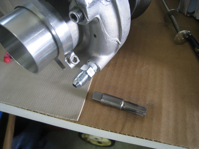
The next PITA issue I encountered was on the compressor signal line port. The port had not been threaded fully so the line could not be connected.
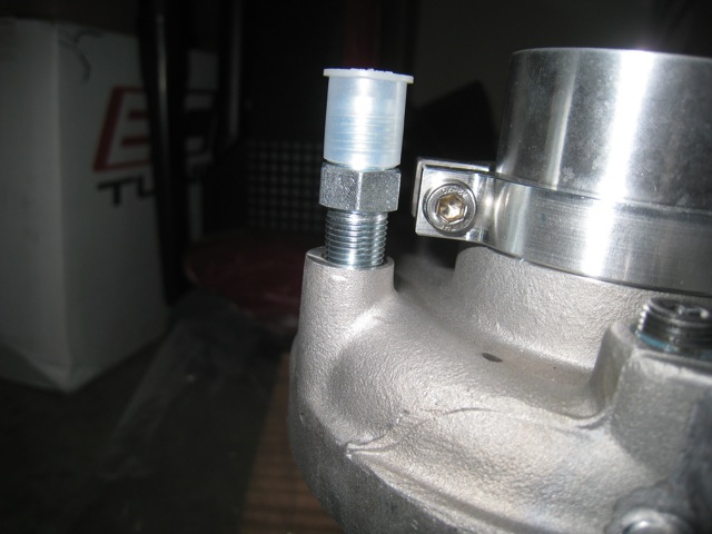
Ultimately following a trip to the local hardware store to purchase a tap we were able to get the compressor line on.
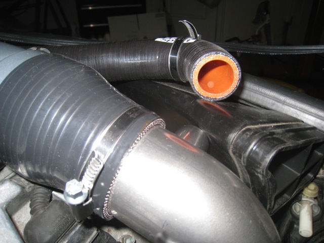
This is another of the planned changes that need to be made to the car’s components. The intercooler inlet pipe needs to be shortened.
Not a big deal, if you’ve got a dremel tool or some other way to cut the pipe to the proper length, but is this “bolt-on”?
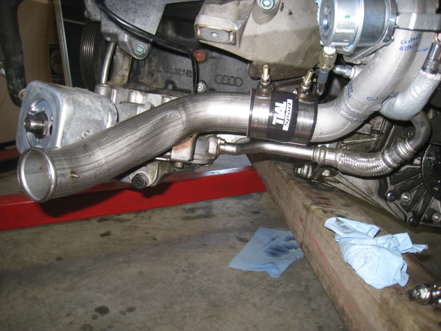
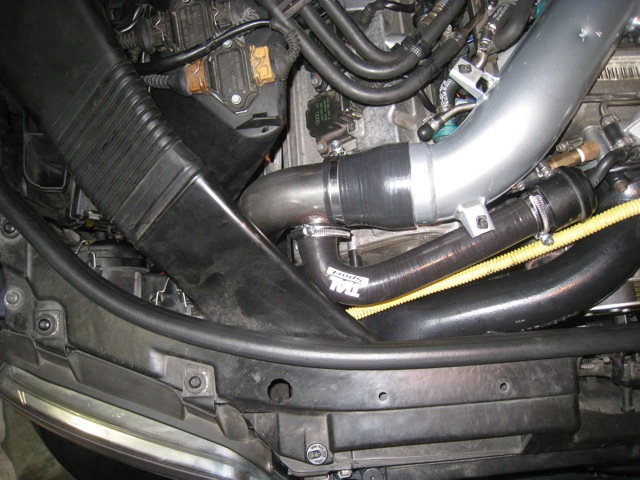
Pipes in place.
With connector hose on.
Break time…. got to keep the volunteer help happy!
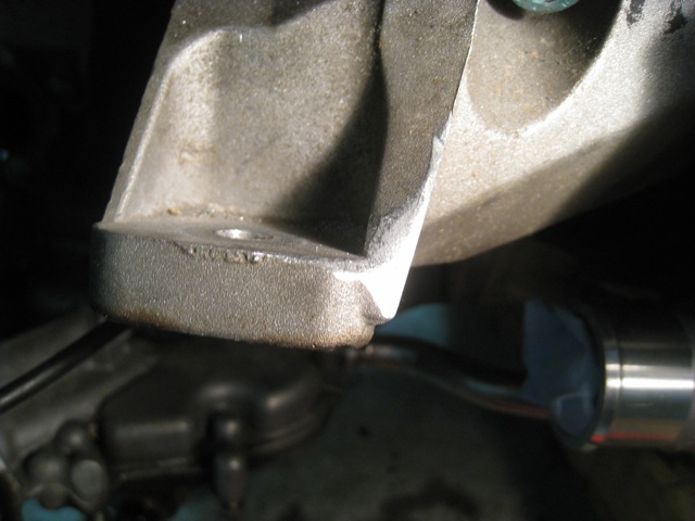
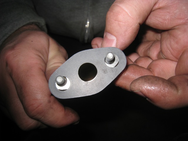
This was a disappointing discovery. The flange between the oil return line and turbo housing was not a real good fit. It wasn’t a huge deal, we just made sure to center it based upon where the edge protruded or was flush, but I would have thought this type of a part would have mated up better.
Finally we got the passenger and drivers side turbo’s installed and hooked up.

Another item that would have caused me some trouble had I not had some expert help on hand was capping off these lines. It wasn’t a big deal to do so, but it wasn’t something I was expecting to do. It wasn’t part of the turbo install, more related to the fueling kit install, and it was never mentioned that this would need to be done.
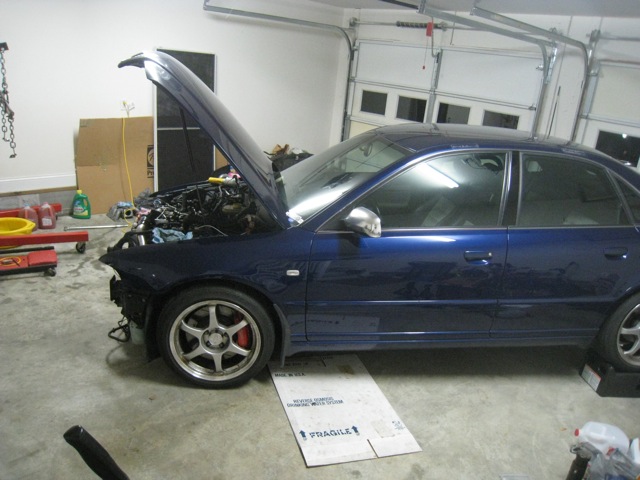
I was waiting a long time to get back to this point, motor back in the car, hooray!
The next challenge was getting the MAF sensor installed. Dave had taken care of soldering the harness in place, but when I went to put the Hitachi sensor into the MAF housing I discovered that the sensor had a slightly different shaped base that prevented it from matching up closely with the MAF housing. I had purchased a used Hitachi sensor from a 2004 Audi, which was the same part number, but I had hoped would be in slightly better condition than a used one from a B5 S4. I’m assuming the design changed slightly over time. The only other possibility was that the MAF housing was machined improperly, but since the housing wasn’t a new design as far as I know, that seems improbable.
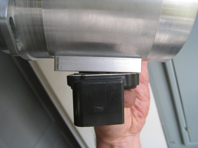
It wasn’t too much trouble to file off the extra plastic and the sensor then fit into the housing fine.
Dave came over with his ticket magnet to check on the progress.

Almost back together.
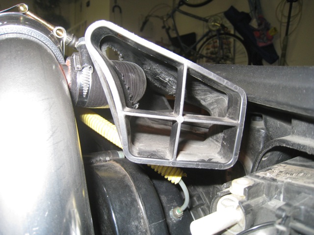
Well I thought I had made it past all of the big challenges, then I tried to reinstall the air intake snorkel. Doh! I couldn’t believe what I was seeing. The TiAL DV recirculation hose was blocking the intake snorkel from being put back into its proper location.
You can see that the snorkel was pushed well to the left of where it should have been. The response from EPL was less than inspiring when they told me none of the 605 kits used the intake snorkel. The idea that I’d just leave the end piece off so that air from the engine compartment would be drawn into the airbox was not the answer I was looking for.
My solution will follow in the next posting.
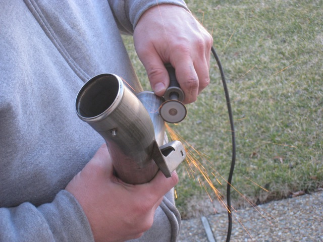
Snorkel Hack Job
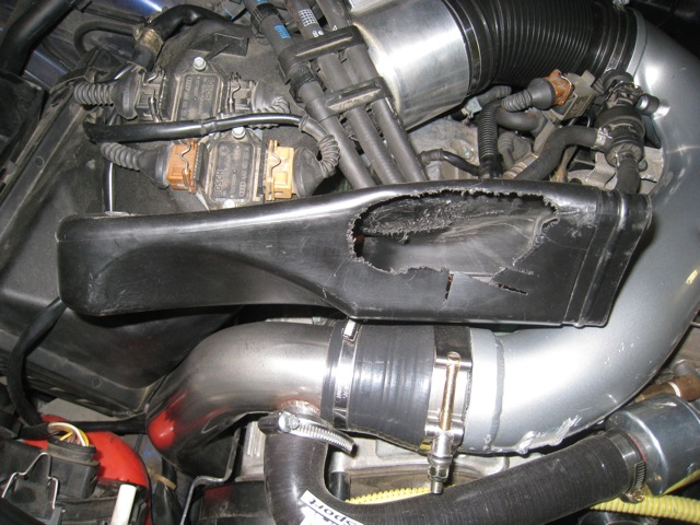
As I had pointed out in the main build thread, the stock snorkel was not intended to be used with this kit. But no solution was offered other than leaving it off. The prospect of having the airbox drawing air from the engine compartment didn’t sit well with me but I drove the car initially that way as I tried to come up with a solution. Finally I decided I would saw out a hole in the side of the snorkel so that the DV recirculation hose could then lay inside the snorkel pipe.
Since I was charting new territory, and I didn’t have precision cutting tools to work with, I simply set about hacking up the snorkel as best I could to fit around the hose. At the present time there are some gaps around the edges, but I figure there’s now much less engine compartment air being ingested by the motor than previously.
Prior to beginning the cutting I had looked into the cost of a replacement snorkel tube, in the event I made such a mess of it that it was no longer functional. The cost of a new part was reasonable so I wasn’t too concerned about possibly making a mess of the snorkel. At this point I may either try and fill around the opening somehow, or look into a new snorkel piece that I can spend more time cutting carefully to fit more snugly.
At the present time there doesn’t seem to be a good solution, other than doing away with the entire stock airbox system and going with one of the aftermarket options, which I wasn’t keen on spending more money to correct shortcomings in the kit.