Several months ago I mentioned that Turbo Concepts was a vendor I was interested in learning a bit more about. The information I could find at the time was looking promising based upon the marketing information, but I was hoping to find some user data on the Stage 1 offering.
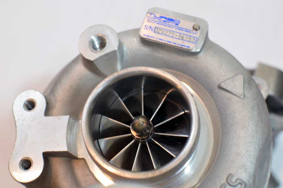
Turbo Concepts DZX-271
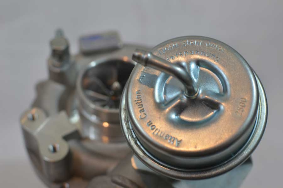
Turbo Concepts (TC) was cooperative in providing me with some on car data, unfortunately the results were from the middle of the summer (hot temperatures), and on a Tiptronic equipped car, so the tune was not very aggressive. The information was inconclusive; it did not show the turbo’s being able to produce full boost by 2800 rpm, something the larger Stage 2 turbo is claimed to do and so a benchmark that I would expect the smaller Stage 1 turbo to equal, or exceed.
For reference, BW K04’s under favorable temperature conditions can reach 20 psi by 2800 rpm. The BW K04 is also advertised to flow about 21 lbs per minute, by comparison the TC Stage 1 product is claimed to deliver up to 28 lbs. per minute.
Outflowing the BW K04 yet retaining the same response is just what I have been after as part of my search for the best stock motor turbo. A search that has yet to uncover a turbocharger capable of equaling the responsiveness of the BW K04. The Turbo Concepts Stage 1 turbocharger is unique among turbochargers I have come across as it is targeted as a direct replacement for the RS4 K04. During my search of the K04 alternatives the information I have found shows that most of these K04-hybrid options are a decent bit larger than RS4 K04’s, and so far have failed to meet RS4 K04 responsiveness.
While inquiring about the TC Stage 1 product they had informed me that they were in the process of incorporating a revised turbine wheel design in their products and that the new turbine wheel was expected to bring an increase in responsiveness, this was encouraging news.
The Stage 1 turbochargers are now available with the latest turbine wheel and I’ve decided to see if this product lives up to the manufacturer’s claims, those being:
BorgWarner RS4/K04 responsiveness
Outflow the BorgWarner RS4/K04 by 20% (28 lbs/min)
Up to 450whp on pump gas
I also plan on assessing how it compares with the other turbochargers I have evaluated on my B5 S4.
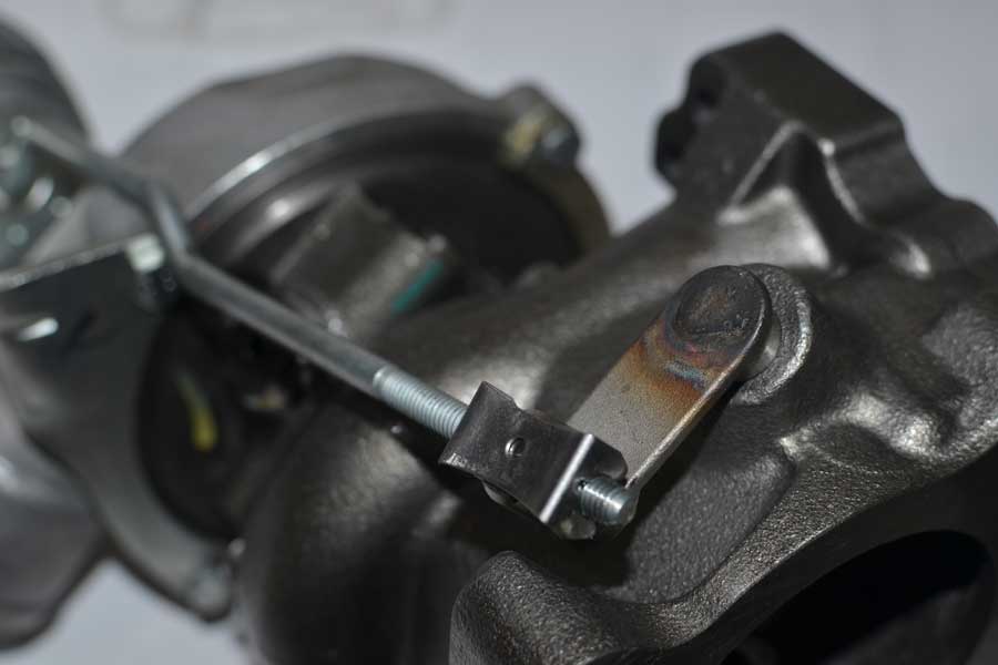
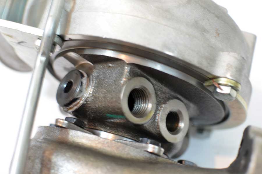
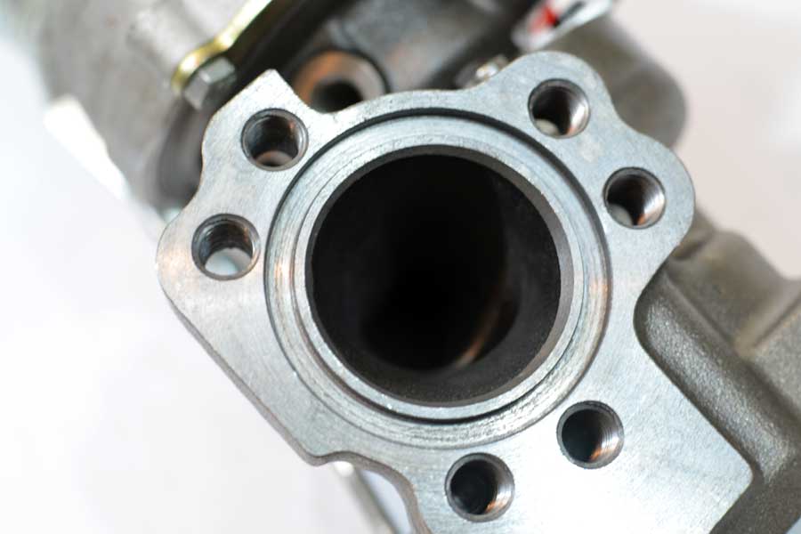
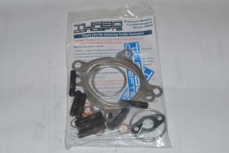
The following are photographs of the Turbo Concepts DZX-271 Turbochargers that were delivered.
With having collected enough performance data on the street about the effect of the AWE Exhaust Manifolds on boost onset and pre-turbine back pressure, there was not much left that I was interested in seeing. Still, with installing exhaust manifolds being a bit of a chore, I decided I would take advantage of having the AWE product installed and dyno my S4.
AWE-Tuning Tubular Exhaust Manifold
I was thinking of ways to make the session a bit more productive other than to just gather more data on the AWE manifolds. I chose to also test the effect that the water-methanol injection system’s nozzle placement has on Intake Air Temperature and the effect, if any, that the Fluidampr harmonic dampener has on torque and power production.
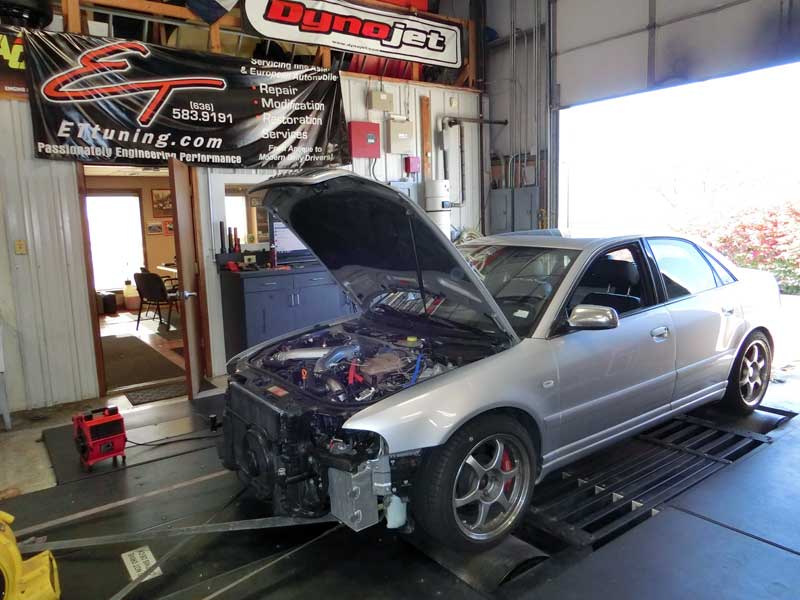
With those three tests planned I arranged for a dyno session at ET Tuning in Union Missouri. As a precursor to the dyno test procedure, and to get an estimate of the amount of time it would take to swap the harmonic dampener, I swapped my S4 back to the OEM part.
First up was a pull with the car configured as I’ve driven it lately – BorgWarner K04 turbochargers, AWE-Tuning tubular exhaust manifolds, and dual 0.4mm Aquamist WMI nozzles placed in the up-pipes. One exception was the OEM harmonic dampener being installed, lately I have driven with the Fluidampr, although my last dyno with the BW K04’s was done with the OEM dampener in place. The tune is unchanged from the last K04 dyno session.
In a post from the day of the dyno I explain the absence of the bumper and headlights. A comparison of the better pull from the earlier session (red line) with the better of the first two (of several) on this day (blue line) is shown below.
BorgWarner K04: Stock S4 vs AWE-Tuning Tubular exhaust manifolds
Nothing particularly remarkable stands out. The torque with the stock S4 manifolds builds more quickly, this could have been expected based on the data that showed the boost building more quickly with the stock exhaust manifolds. On the dyno the boost profiles are (solid lines stock, dashed lines AWE):
Stock Exhaust Manifolds vs AWE-Tuning Tubular: Boost Onset
With the AWE-Tuning manifolds the boost is about 200 rpm behind that of the stock exhaust manifolds, although the curves do start slightly later with the AWE manifolds. The initial boost swing of the stock curves is not a byproduct of the stock exhaust manifolds as I only saw that response on the dyno the day the first logs were recorded.
Tabulating the peak torque and horsepower numbers from all the runs on both days and comparing them, with the stock exhaust manifolds the car made 8 more wheel TQ and 5 less wheel HP than when equipped with the AWE-Tuning exhaust manifolds.
Notably from the datalogs, the AFR during the AWE manifold runs was almost three-quarters of a point richer than the stock manifold runs – potentially altering the power numbers from where they would have been (higher) had the AFR been the same between sessions.
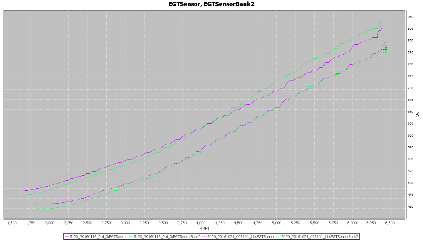
Comparing the Exhaust Gas Temperatures on two pulls that had similar starting conditions:
The rate of temperature increase with both exhaust manifolds is approximately the same. This is not a surprise since the duration of a dyno pull is relatively short.
This test produced no surprises. Aftermarket exhaust manifolds predominantly are built to improve airflow, or more correctly reduce pressure losses at high airflow rates, a result of this is a reduction in air speed through the manifold runners as compared to the stock manifolds. This lower air speed decreases the available energy for spooling up the turbochargers giving the delayed boost onset and slightly reduced low-end torque in favor of better top end horsepower.
In my case, with a small turbocharger and a modest boost profile the effects are minimal, but present.
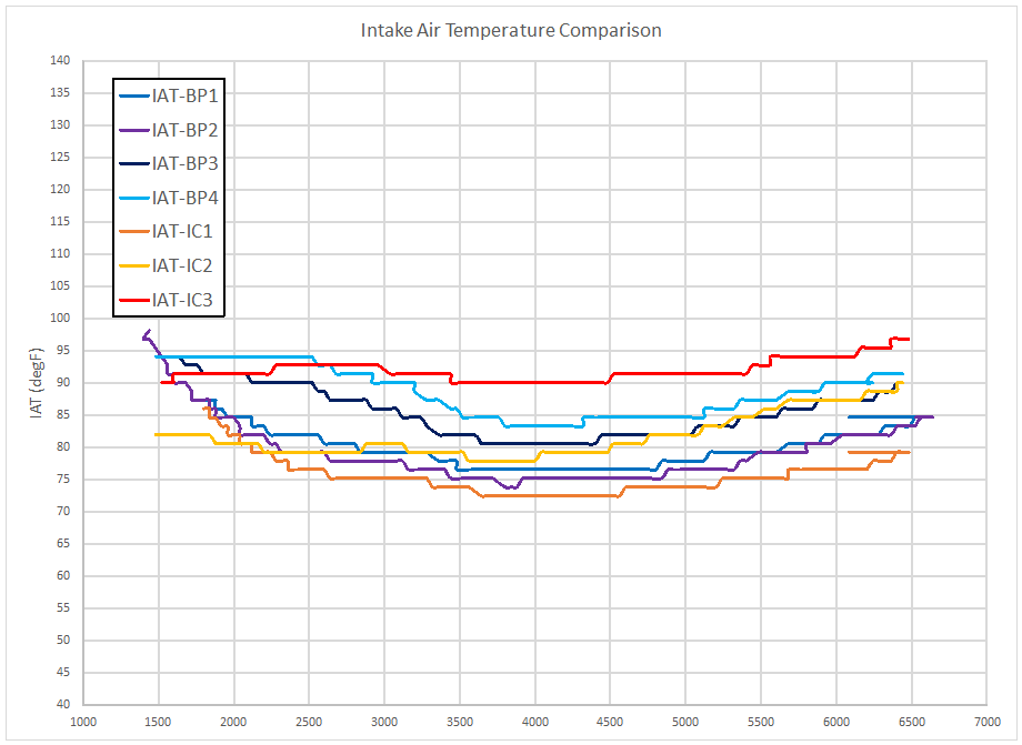
The next test was to find if the location of the water-methanol system nozzles would affect the intake air temperature.
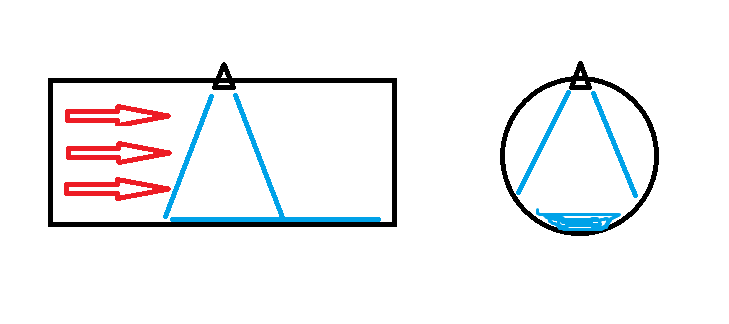
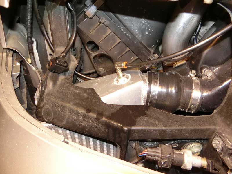
One of my concerns with the placement of the nozzles in the up-pipes is the potential for a significant amount of the injected fluid to impinge the side walls or opposite side and collect in a stream that does little to help cool the charge air. This concern had prompted a request for a set of intercoolers with wmi bungs located in the end tanks such that the injection of water-methanol would be almost directly into the oncoming airflow, thus gaining better mixing of the fluid and air. This placement in the end tanks is shown below.
WMI Nozzles in SMIC end tanksWMI Nozzle – Passenger Side ICWMI Nozzle in driver side IC end tank
Several pulls were conducted with the wmi nozzles in the bipipes and the SMIC end tanks. A compilation of the intake air temperature data is shown below:
Nozzle placement comparison
There does not seem to be any obvious difference in the temperature profile with change in nozzle placement.
Flow rates were also unaffected:
Pulls 1-2Pulls 3-7
Note that on pull 2 (F2-V2) on the top chart and pull 5 (F3-V3) on the lower chart that these pulls are after the WMI hose line was swapped and the initial spike in flow rate is on account of the line being filled.
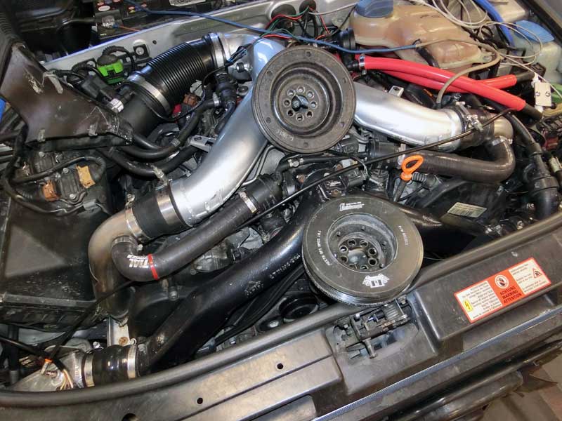
The last test was the most involved labor-wise. Swapping out the OEM harmonic dampener for the Fluidampr.
Preparing for Fluidampr swap
Ready to install the Fluidampr:
OEM (top) and Fluidampr (bottom) harmonic dampeners
As it turned out, the Fluidampr pulls proved to be the most involved to decipher. When comparing the peak numbers of the OEM harmonic dampener versus Fluidampr the swap caused the torque to drop 8 ft-lbs and the power to drop 13 horsepower.
The immediate deduction was the added mass of the Fluidampr is slowing the rotation rate of the crankshaft and diminishing the output. Knowing how the intake temperatures can affect power production I looked into how the power numbers changed with the smallest recorded IAT of the pull.
The correlation is very strong, so much so that I needed to do more than a simple comparison of peak numbers to deduce what the Fluidampr may have done to engine performance.
In the chart above the green dots are with the OEM harmonic dampener and the red dots are with the Fluidampr. The orange dot is also with the Fluidampr, but was the first pull after the hour-long break while swapping the parts.
If the number of Fluidampr data points is limited to the pair that have IAT’s similar to that with the OEM part then the difference is only a drop of 3 ft-lbs and 10 horsepower.
Unfortunately one of the two good IAT datapoints happens to be the orange dot, the pull that was first after having the car sitting, and cooling, on the dyno for an hour. If I take the single reliable datapoint for the Fluidampr, the difference is 1 ft-lb and 4 wheel horsepower, a minuscule difference when comparing values of around 430 ft-lbs wtq and 400 whp.
The dyno chart for this ‘best case’ comparison is shown below with the Fluidamp pull highlighted by the green line.
OEM vs Fluidampr
Results with the Fluidampr are not conclusive, but it does not seem engine power production was increased with the aftermarket harmonic dampener. This is not all that surprising since the function of the part is not to increase power but help to control harmonic vibrations.
Today the Silver S4 went back to the Dyno for a series of pulls with some hardware configuration changes. Data from that is still under evaluation.
10/21/2016 Dyno Session
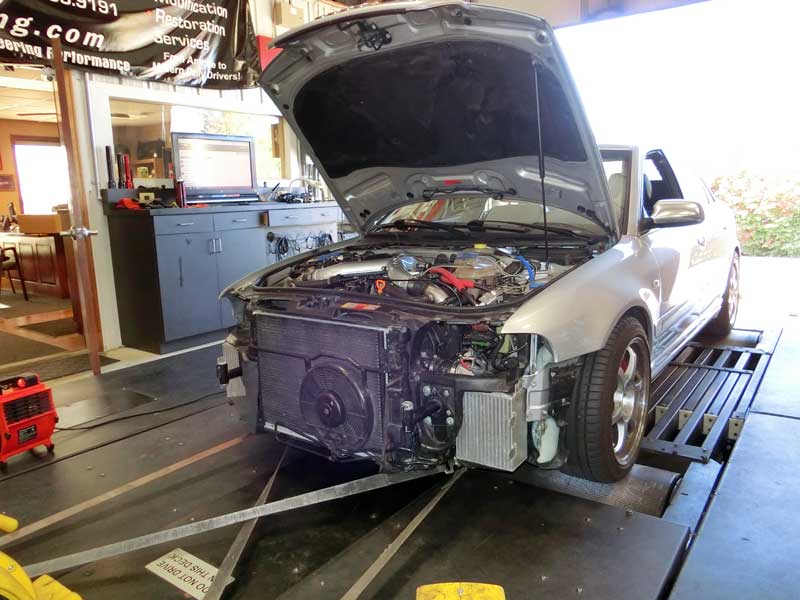
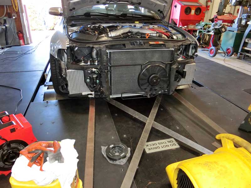
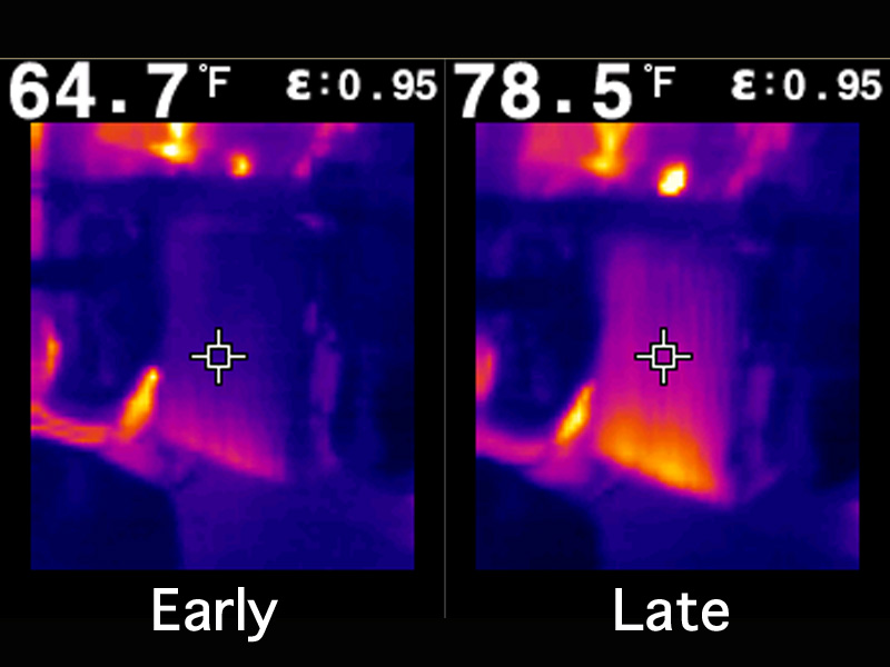
Because I was changing some hardware configurations I removed the front bumper and headlights for the morning. This allowed me a clear view of the intercoolers, or more correctly the thermal camera a clear view of the intercooler.
I snapped these images during one pull, the left image is from the early part of the pull and the right image is from the last part of the pull as the dyno operator lets off the accelerator.
SRM SMIC Thermal Image During Dyno Pull
As makes sense, the lower part of intercooler, where the charge air enters the core, is rising in temperature more rapidly than the upper part of the core, where the cooled air exits.