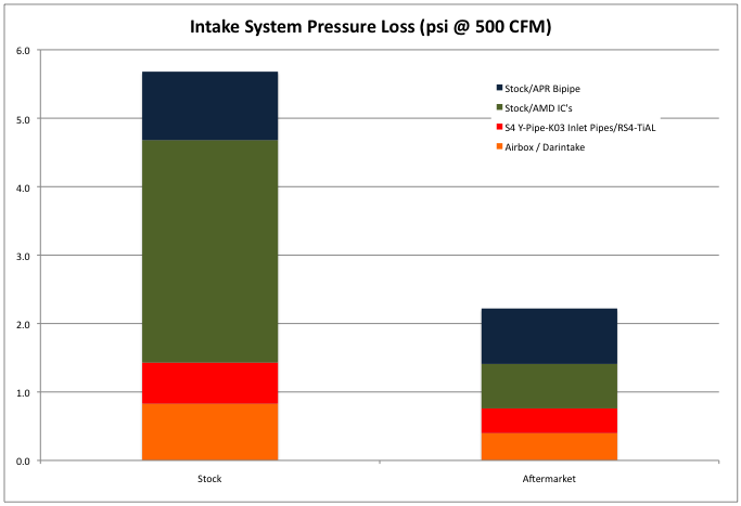
The chart below shows an approximation for how the stock B5 S4 intake system compares against an aftermarket alternative. The various system components were tested separately, so the composite results shown below do not accurately depict how all of the parts would measure if operating on the automobile.
Additionally, when on the vehicle the operating pressure would in many cases be much higher, which would cause the pressure losses to be greater. Still, the chart gives some indication to the scale of improvement that can be obtained through the use of aftermarket or alternative parts, at the tested airflow of 500 CFM.
The legend shows the different configuration tested. To the left of the slash ( / ) is the stock configuration and to the right is the modified and/or aftermarket configuration.
The following information is a summary of data I have personally recorded as well as information I have obtained by viewing the results provided by others.
This information should not be taken as ground truth, there can be variability in results dependent upon how a car is operated, what environment it is evaluated in, and how the information is collected. The point of presenting this data is to make available to others the information that I use.
In the following scatterplot, products for which I do not have IAT data are shown along the vertical axis at an IAT Rise value of zero.
I received a FrankenTurbo Y-Pipe prototype to evaluate the flow characteristics of. On hand I also have an RS4 y-pipe and stock S4 y-pipe as shown in the lineup below.
The FrankenTurbo prototype utilizes a stock size entry (80mm) and a larger outlet of 59mm, compared to the stock y-pipe outlet measuring 51.5mm. For comparison, the RS4 y-pipe has 65mm outlets.
When put on the flow bench and tested at 10″ H2O the following results were obtained:
It was agreed that the results of the FrankenTurbo prototype were less than hoped for. While the outlet diameter of the FrankenTurbo y-pipe were 15% larger in diameter than stock, the airflow had increased only 6% over the stock y-pipe.
By comparison, the RS4 y-pipe has an outlet diameter 26% greater than stock, and the airflow recording was 28% greater than stock. Even the removal of the metal outlet pipes, leaving just the silicone portion of the y-pipe, with outlets measuring 62mm in diameter, failed to improve the airflow of the FrankenTurbo prototype.
My suspicion is that possibly the coefficient of friction between the FrankenTurbo’s silicone hose and air is greater than that with the aluminum wall of the RS4 y-pipe.
Next a set of FrankenTurbo turbo inlet pipes were provided to test in conjunction with the FrankenTurbo y-pipe and also when paired with the stock y-pipe.
These results are shown below along with similar configurations of the RS4 y-pipe and TiAL 2.25″ inlets. Note, the TiAL inlets are the same diameter as the FrankenTurbo inlets.
The FrankenTurbo coupler cannot be used with the RS4 y-pipe due to the outlet of the RS4 y-pipe being larger than the FrankenTurbo y-pipe prototype outlet.
In the chart above I have highlighted a very unusual result of this testing. The stock S4 y-pipe will flow approximately 385 CFM with nothing attached to it. When the FrankenTurbo coupler hoses were attached to the y-pipe the airflow INCREASED, rising to 401 CFM, a 4% gain in airflow by attaching the coupler hose.
Unlike with the stock y-pipe, when the coupler is attached to the FrankenTurbo y-pipe the airflow drops, by about 6%. The testing was repeated with the RS4 y-pipe and the coupler used to connect with the TiAL inlets, again a drop of approximately 6% was recorded for the airflow.
Additionally, when the stock K03 coupler hoses are attached to the stock y-pipe the airflow through the stock y-pipe decreases slightly.
My guess for why this is occurring is, the RS4 y-pipe and FrankenTurbo y-pipe prototype both constrict the airflow at the exit point, causing an increase in back pressure relative to how the y-pipe performs without the coupler in place. The stock y-pipe does not see a similar constriction at the outlet when paired with the FrankenTurbo coupler. That would seemingly be helpful, but one would expect that the airflow rate would be relatively unchanged whether the coupler was used or not, increasing the airflow through the y-pipe is an unexpected result.
Looking at the outlet area of the stock y-pipe it is apparent that there are two dimples on the lower side of the pipe, corresponding to protuberances on the exterior which provide a stop for the coupler hose. This location of these dimples means that just prior to the outlet the piping is not smooth, promoting turbulence. My theory is that the turbulence being created by these dimples enables a high pressure region to form just before the y-pipe outlet, adding to pressure losses through the pipe.
So why not also occur when the coupler is in place? My theory is that the additional channel created by the coupler keeps the air stream in-line and prevents the formation of the high pressure zone. The video below also shows what appears to be a strong vortex along the upper side of the coupler and this may also be helping with preventing the formation of a high pressure zone at the outlet.
* – Just to re-emphasize the explanation given above is just a theory and without some more sophisticated measuring devices this phenomena may remain a mystery.