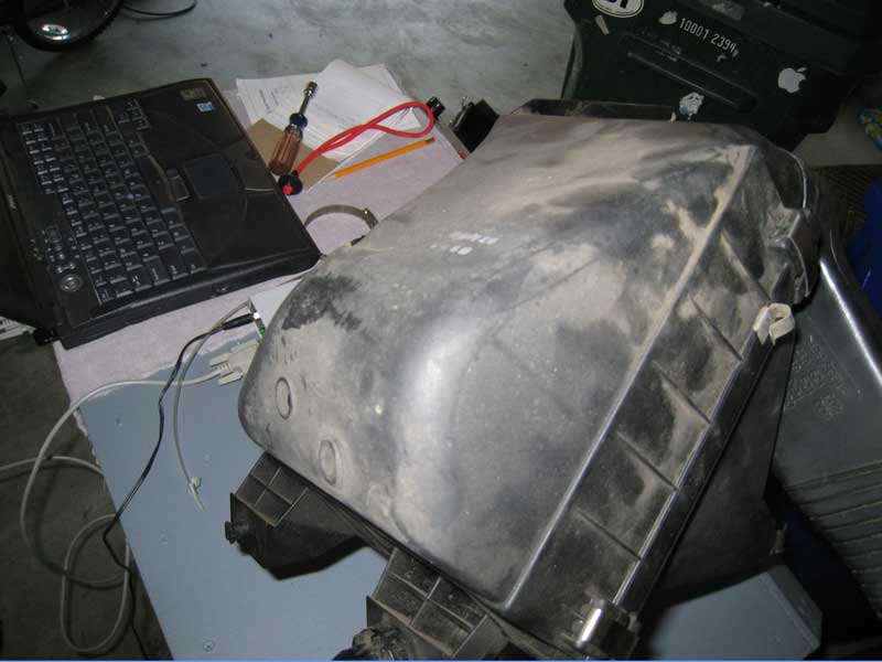
Reason: I decided to do an airbox flow test because cutting the bottom out of the stock air box is a popular modification to improve the airflow to the motor. At a certain power level this change is necessary as the accordion hose collapsing under vacuum gives indication of. The extent of the modification needed to the air box is something that is not well defined and I have observed air boxes that have nearly the entire lower portion cut off.
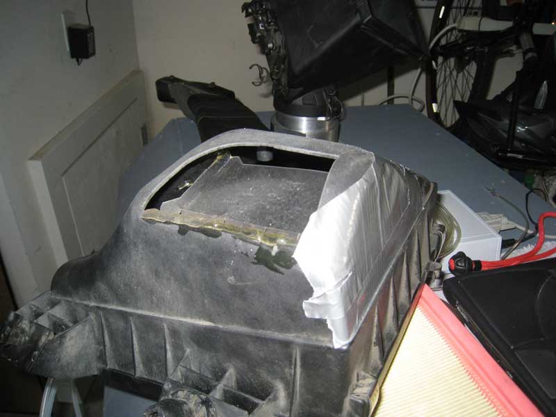
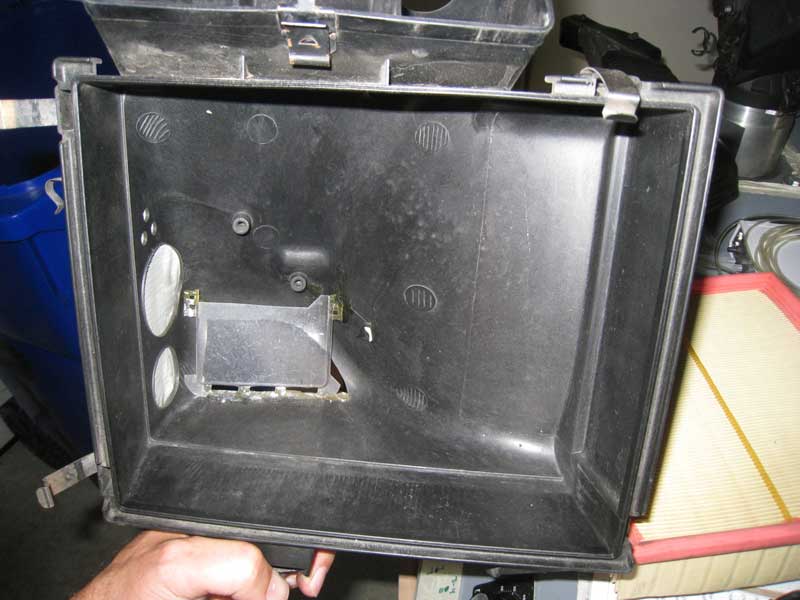
After finding that my air filter would get wet from water spraying up from the wheel well I decided to add a baffle to the opening in my airbox to prevent the entry of water into the airbox. I also added some holes to the front side of the airbox, which faces the front of the car, similar to the port located on the RS4 airbox.
I was interested in finding out how much additional airflow would be possibly through these modifications so I took a stock airbox as a baseline and recorded the airflow through it. Next I taped up all of the additional holes on my modified airbox except for the opening with the baffle. The test was repeated and then additional tests were performed incrementally opening more of the passages.
All testing was done with the intake snorkel in place.
Airbox Flow Test Results:
Flow values are estimated to a depression of 28″ H2O for all configurations except for stock since the maximum airflow capacity of the flow bench is approximately 600 CFM @ 28″ H2O and with the modification the air box was able to flow more air than the bench could draw through at 28″ H2O.


Update: Additional configuration testing
I decided that I did not care for the three small holes so I replaced them with a single larger hole that would allow more air to flow through. Doing so picked up 11 CFM over the previous configuration.
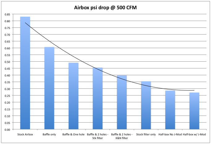
Making this change and seeing the resulting increase in airflow made me realize that it would also be insightful to measure the pressure drop at a particular airflow. While increasing the airflow at a fixed depression is useful for optimizing a device, such as what is done when porting, it doesn’t give a number for how much less pressure drop there is. If all of the additional holes only improve pressure drop a tenth or two psi, it may not be worth the effort.
The next test on the airbox that I conduct will involve the same configurations as shown on this page, but will evaluate the change in pressure drop at a fixed CFM.


No snorkle – Airbox as it would be configured inside the vehicle except the entire snorkel was removed.
Filter only – All air box and intake parts prior to the air filter were removed. See pic above.
No filter, rest of box – Air box and intake as would be found on the vehicle with the air filter removed.
Nothing, half box – Just the portion of the air box that attaches to the MAF sensor housing. See pic above.
* Note – All testing was done with a Hitachi MAF sensor in the MAF housing.
More results
The chart below shows the results recorded for pressure drop occuring at 500 CFM. For reference, I estimate that at 22 psi and 7000 rpm with an 85% VE there should be around 700 CFM passing through the airbox.

Neither the stock air filter nor the K&N panel filter were new.
The curve is a second order polynomial fit just to give a better sense of the trend.
More on the J-Mod in another report to come.
Additional related flow testing can be found on the MAF flow test page where I also include an RS4 airbox.
