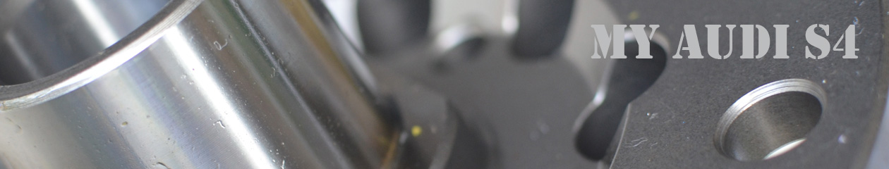
A set of TTE550’s has arrived for evaluation. The turbochargers came well packed and even included a balance sheet for each turbo, a nice addition for turbo’s that have been rebuilt to upgrade the BorgWarner K04’s to a hybrid using a variant on the RS6 center.
TTE550 RS4 K04 Hybrid Turbochargers
Looking them over it dawned on me that the ring that goes around the wastegate canister increases the effective diameter of the canister, and I have encountered problems fitting the TiAL turbo inlets past the BW K04 wastegate canisters. This could lead to future headaches when I start installing these turbo’s. The ring can be loosened and rotated, hopefully that will be enough to avoid problems fitting them alongside the inlets
I next turned my attention to giving the TTE550 a turn on the flow bench, something I have done with the BorgWarner K03 and K04 products in the past. First though I’d have to remove the turbine housing studs so I could fit the turbine housing flush to the flow bench.
I’ll just twist this first stud out, or maybe not. Vice grips, nope. Penetrant oil & heat, nope. F*******ck. Not coming out. Looks like I’ll be making a trip to a machine shop to have the studs removed.
Until that takes place I won’t be making any progress with further evaluating these TTE550 turbocharger’s.
Through the process of recording Intake Air Temperature (IAT) I have pretty well beat this subject to death, not finding much, if any, benefit to the charge air temperatures by having shrouds in place on the intercoolers that I have used in the past.
These results have been counter intuitive, so much so that I continue to purchase shrouds with my intercoolers even though I haven’t found them to improve the performance of the intercoolers.
To try and better understand why the shrouds don’t seem to be beneficial I decided to look at assessing the problem in a different way. I thought that if I could place a MAF sensor housing flush against the back side of the intercooler core I should be able to record the mass airflow through the core under a variety of conditions.
Since I have tried checking the MAF voltages on the flow bench in the past I was close to having a setup that I could transfer onto the car with little difficulty. Mounting the MAF housing to the back of the core was one concern that I thought could prove frustrating to try and accomplish. I discovered during test fitting, to see if the MAF would even fit behind the core, that a couple of the cars interior braces would allow me to wedge the MAF housing in place and it would be flush against the core, good news. All I needed to do was figure out how to hold the MAF housing in place. After checking a couple of different length bungee cords I found a good length and wrapped it around the MAF housing. A nice snug fit and the housing was firmly locked in place.
Hitachi MAF housing behind SRM IC core
Next I set out to record the MAF voltages under different driving conditions with different parts on the car.
The first test case was without shrouds on the intercoolers. I also left the belly pan off for this drive. The route I took had me driving at 10 mph and then 20 mph through my neighborhood. Out onto a street where I drove 25 mph then 30 mph. Onto another street where I could drive 40, 45, 50, and 55 mph. The onto a highway where I drove 60, 65, 70, and briefly on one drive 75 mph.
This drive was repeated with a stock shroud in front of the IC core. I chose the stock shroud because the shroud supplied with the SRM IC fit’s very poorly and has a large gap along one side of the IC core. The stock shroud has a good fit and the air is funneled into a region of the IC core that the MAF housing sits behind.
The final configuration that I recorded today was with the addition of the belly pan to the shrouded IC.
Shrouding MAF Test
On the chart above the Red lines are the “No shrouds” drive. The Green lines are with “Shrouds” but no “Belly Pan”. The blue lines are for the case with both the “Shrouds” and “Belly Pan” installed.
Upon first glance it looks like adding the shrouds did improve the mass flow rate through the IC core. It also looks like the belly pan did not have much of an affect on the flow through the core.
I need to further analyze the data so that the speed versus time differences are eliminated and I can compare flow rates at like speeds.
A final test case I plan to evaluate will be with the IC shroud removed, but under belly pan in place.
Conclusion:
While this more direct measurement of airflow through the core showed differences with and without the shroud in place, I am unsure if the differences are significant enough to cause a meaningful change in the charge air temperature exiting the IC core.
Continuing to establish some baseline performance metrics for the K04 turbo’s, I recorded the exhaust pressure pre-turbo with K04 turbochargers on the car, stock exhaust manifolds, and a mild Stage 3 tune.
The pressure sensor reads on the passenger side exhaust manifold where the EGT sensor is normally attached. I have a few connections leading from the exhaust manifold so that the sensor is not close to the exhaust gas heat. The sensor is laying next to the accordion hose in the photo above.
A change from when I made these recordings with the K03 turbo’s is the addition of a pressure snubber to the signal line. This device helps to smooth out pressure pulses to produce a smoother input signal and to also protect the sensor.
Pressure Snubber
Results with the current turbo’s and tune are displayed below: